
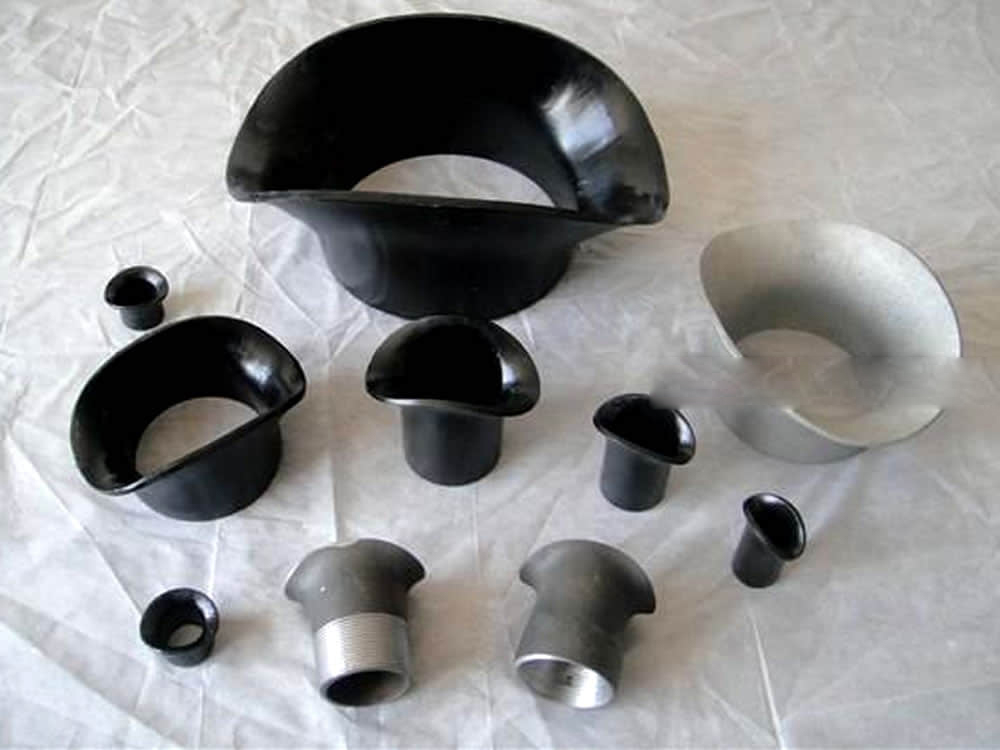
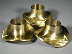
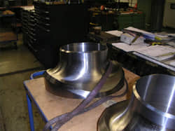
A saddle previously, also referred to as pipe saddle lateral tees, has a shape resembling a pair of pants and is available in two variations: equal diameter and unequal diameter.
There is no standard size, to be based on three tube spacing center line of the front and graphic design draw graphics, Lofting produced, lofting a certain degree of difficulty.
We are manufacturer of Saddle previously and supply high quality Saddle previously in both large and small quantities worldwide & offer you the best prices in the market.
Size range: 1/2 to 72 inches

Sweepolet Saddle, Steel Saddle, Carbon Steel Saddle, Stainless Steel Saddle, Alloy Steel Saddle
Saddle previously is to replace the existing tee fitting, the use of flexibility, praised by domestic and foreign markets.
A saddle fitting, also known as a saddle clamp or simply a saddle, is a type of pipe fitting designed to connect a smaller diameter pipe or tube to a larger one. It resembles the shape of a horse saddle, with a curved structure that wraps around the larger pipe while accommodating the smaller one. This design allows for a secure and leak-resistant connection between pipes of different sizes.
Saddle fittings have a rich history and have been employed in a range of applications across various industries. Here are some examples of how saddle fittings were previously used:
In agricultural settings, saddle fittings were commonly used in irrigation systems. They facilitated the connection of smaller distribution pipes to larger mainline pipes, allowing water to be efficiently transported to different areas of a field.
Saddle fittings found their place in plumbing and drainage systems, especially in scenarios where new branch lines needed to be added to existing pipelines. The saddle provided an effective way to create a connection without disrupting the entire system.
Industries that required the transport of various fluids, such as chemicals or wastewater, often used saddle fittings to create connections for sampling, monitoring, or additional outlets.
Saddle fittings were also used in gas distribution networks, allowing for the connection of gas lines of different sizes and enabling the safe and efficient distribution of gases.
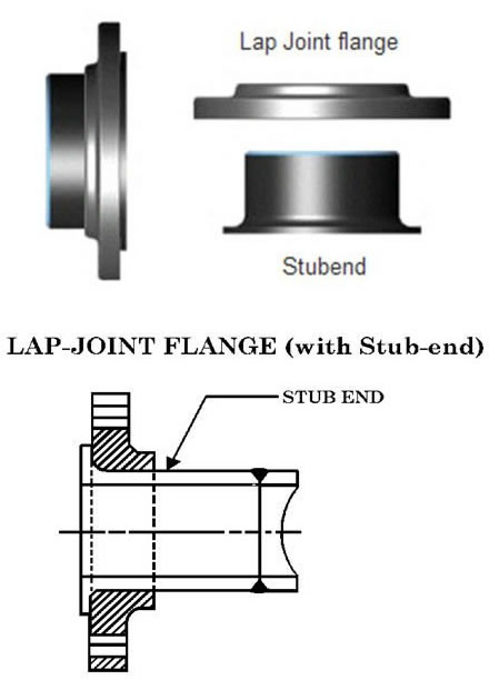
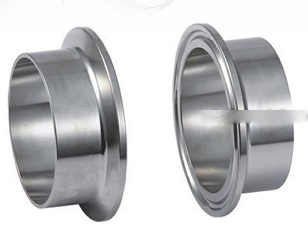
Stub end are offered in three different ways, type A, B and C. Type A and B stub end are similar to forged fittings, such as elbows and tees, and type C stub end are made in customized sizes. Stub ends are manufactured in three different types and two standard length. Type “A”: this type is produced and machined to fit lap joint flanges.The mating surfaces of the stub end and the lap joint flange have a matching profile and surface. The lap thickness of type A stub ends is > = the minimum wall thickness of the connected pipe. The outside the stub end and the lap joint flange have a matching profile and surface. The lap thickness of type A stub ends is > = the minimum wall thickness of the connected pipe. The outside corner of type A has a radius to accommodate the lap join flange, whereas the inside corner is squared. Type “B”: this type of stub ends is suited for standard slip-on flanges acting as lap-joint flanges. The lap thickness of type B stub ends is >= the minimum WT of the connecting pipe. The lap of these type of stub ends has generally a serrated face. To ensure tight joints, chamfers on the ID side of the flange are required. Type “C”: this last type can be used both with lap joint and slip-on backing flanges and are fabricated out of pipes. The lap of C-type stub ends is flared over and the lap thickness is 75% of the connecting pipe WT. Type C has a short fillet outer radius able to host any back up flange. Type “CS”: this type is similar to “C” with the difference that the lap face has concentric serrations machined during the manufacturing process. There are two main types of stub ends commonly used in piping systems: Long Pattern Stub End: A long pattern stub end has a longer length compared to the pipe it is attached to. It is designed to be used with standard lap joint flanges. The long pattern allows for easier alignment and welding of the lap joint flange, making it suitable for applications where frequent disassembly is required. Short Pattern Stub End: A short pattern stub end has a length that is similar to the pipe it is connected to. It is used with slip-on flanges, where the stub end slides over the pipe and is welded in place. The short pattern stub end is ideal for applications where space is limited, and the flange needs to be close to the end of the pipe. Both long pattern and short pattern stub ends are available in various materials such as stainless steel, carbon steel, alloy steel, and others, making them suitable for different industrial applications. They provide a cost-effective and reliable solution for connecting pipes to flanges in piping systems. Dimensions and manufacturing tolerances are covered in ASME B16.9 – Butt Weld Fittings and MSS-SP-43 (JIS B2312, JIS B2313 may also apply). Stub End come in three standard lengths, MSS SP43 or ANSI B16.9 short and long pattern. Short pattern stub ends are mostly used for flanges from class 300 to class 600 and above. Besides these standard types, End-Users and contractors can require stub ends with non-standard lengths to suit specific project’s requirement. This will of course come at an additional cost. ASME B16.25 END WELDING BEVEL as right The following types of ends may be ordered: Beveled Ends (generally ASME B16.25) Pipe fitting dimensions are in either metric or Standard English. Because pipe fitting covers Pipe Fitting Dimensions several aspects, only the most common pipe fitting sizes can be given here. The most applied version is the 90° long radius and the 45° elbow, while the 90° short radius elbow is applied if there is too little space. The function of a 180° elbow is to change direction of flow through 180°. Both, the LR and the SR types have a center to center dimension double the matching 90° elbows. These fittings will generally be used in furnesses or other heating or cooling units. Some of the standards that apply to buttwelded fittings are listed below. Many organizations such as ASME, ASTM, ISO, MSS, etc. have very well developed standards and specifications for buttwelded fittings. It is always up to the designer to ensure that they are following the applicable standard and company specification, if available, during the design process. Some widely used pipe fitting standards are as follows: ASME: American Society for Mechanical Engineers ASTM International: American Society for Testing and Materials AWWA: American Water Works Association AWWA About – Established in 1881, the American Water Works Association is the largest nonprofit, scientific and educational association dedicated to managing and treating water, the world’s most important resource. ANSI: The American National Standards Institute ANSI is a private, non-profit organization. Its main function is to administer and coordinate the U.S. voluntary standardization and conformity assessment system. It provides a forum for development of American national standards. ANSI assigns “schedule numbers”. These numbers classify wall thicknesses for different pressure uses. MSS STANDARDS: Manufacturers Standardization Society Difference between “Standard” and “Codes”: Piping codes imply the requirements of design, fabrication, use of materials, tests and inspection of various pipe and piping system. It has a limited jurisdiction defined by the code. On the other hand, piping standards imply application design and construction rules and requirements for pipe fittings like adapters, flanges, sleeves, elbows, union, tees, valves etc. Like a code, it also has a limited scope defined by the standard. Factors affecting standards: “Standards” on pipe fittings are based on certain factors like as follows: BSP: British Standard Pipe BSP is the U.K. standard for pipe fittings. This refers to a family of standard screw thread types for interconnecting and sealing pipe ends by mating an external (male) with an internal (female) thread. This has been adopted internationally. It is also known as British Standard Pipe Taper threads (BSPT )or British Standard Pipe Parallel (Straight) threads (BSPP ). While the BSPT achieves pressure tight joints by the threads alone, the BSPP requires a sealing ring. JIS: Japanese Industrial Standards This is the Japanese industrial standards or the standards used for industrial activities in Japan for pipe, tube and fittings and published through Japanese Standards Associations. NPT: National Pipe Thread National Pipe Thread is a U.S. standard straight (NPS) threads or for tapered (NPT) threads. This is the most popular US standard for pipe fittings. NPT fittings are based on the internal diameter (ID) of the pipe fitting. BOLTS & NUTS We are manufacturer of Flange bolts & Nuts and supply high quality AN: Here, “A” stands for Army and “N” stands for Navy The AN standard was originally designed for the U.S. Military. Whenever, a pipe fitting is AN fittings, it means that the fittings are measured on the outside diameter of the fittings, that is, in 1/16 inch increments. For example, an AN 4 fitting means a fitting with an external diameter of approximately 4/16″ or ¼”. It is to be noted that approximation is important because AN external diameter is not a direct fit with an equivalent NPT thread. Dash (-) size Dash size is the standard used to refer to the inside diameter of a hose. This indicates the size by a two digit number which represents the relative ID in sixteenths of an inch. This is also used interchangeably with AN fittings. For example, a Dash “8” fitting means an AN 8 fitting. ISO: International Organization for Standardization ISO is the industrial pipe, tube and fittings standards and specifications from the International Organization for Standardization. ISO standards are numbered. They have format as follows: “ISO[/IEC] [IS] nnnnn[:yyyy] Title” where ASTM A403 Standard specification covers the standard for wrought austenitic stainless steel fittings for pressure piping applications. For each reduction of 0.01% below the specified C maximum, an increase of 0.06% Mn above the specified maximum will be permitted, up to a maximum of 1.35%. The sum of Cu, Ni, Cr, and Mo shall not exceed 1.00%. The sum of Cr and Mo shall not exceed 0.32%. The maximum carbon equivalent (C.E.) shall be 0.50, based on heat analysis and the formula C.E.=C+Mn/6+(Cr+Mo+V)/5+(Ni+Cu)/15. Material Furnished to this specification shall conform to the requirements of specifications A960/A960M including any supplementary requirements that are indicates in the purchase order. Failure to company with the common requirements of Specification A960/A960M constitutes non-conformance with this specification . In case of conflict between this specification and Specification A960/A960M , this specification shall prevail. Material Furnished to this specification shall conform to the requirements of specifications A960/A960M including any supplementary requirements that are indicates in the purchase order. Failure to company with the common requirements of Specification A960/A960M constitutes non-conformance with this specification. In case of conflict between this specification and Specification A960/A960M , this specification shall prevail. The standard includes several grades of austenitic stainless steel alloys, and uses the WP or CR prefix to mark the grade of steel, depending on the applicable ASTM or MSS size and rated pressure standards. ASTM A403 is designed for forged steel pipe fittings, Cast pipe fittings are not suitable. Stub ends are essential components used in various industrial applications, particularly in piping systems. The use of stub ends has these two advantages: Reduces the overall cost of the flanged joint Generally, the lap joint flange is of a lower grade than the material of the stub end and the pipework, thus saving the total weight of high-grade material used for the flanged joint. Reduces the overall cost of the flanged joint Generally, the lap joint flange is of a lower grade than the material of the stub end and the pipework, thus saving the total weight of high-grade material used for the flanged joint. Example: For an SS316 pipe, instead of using a full 316 welding neck flange, a combination of an SS316 stub end and a carbon steel lap joint flange would do the same exact job, but the total weight of SS316 material would be lower, and the cost as well. Essentially, stub ends allow to minimize the weight of high-grade material in stainless, duplex, and nickel alloy piping, saving costs. Of course, the bigger the diameter and the class of the flanges, the higher the saving! Commercial advantages are that the Stub End, will be wetted and it must be made of a grade of material that meets the process design and service conditions of the pipeline. However, the Lap Flange is un-wetted and it can be made of a lower grade of material as long as it meets The “loose” Flange concept of a Lap Joint, is very beneficial during field installation of piping systems. If two spools are to be mated up in the field, having one Flange that can be rotated is very advantageous when aligning the bolt holes, prior to the introduction of the Stub bolt and the accompanying nuts. The facility of easier orientation and alignment of bolt holes, is of particular use it there is a spool that While stub ends offer numerous advantages in piping systems, it's essential to also consider their limitations. Being aware of these limitations helps engineers, designers, and operators make informed decisions when selecting fittings for specific applications. Let's explore some of the key limitations associated with stub ends: Stub ends, particularly those used in lap joint flange connections, often have lower pressure ratings compared to fully welded or threaded alternatives. This limitation makes them unsuitable for high-pressure applications. Stub ends are typically made from materials that can be easily formed and welded, such as stainless steel and carbon steel. However, they may not be compatible with certain materials like exotic alloys or non-metallic materials. In applications where there is significant vibration, movement, or mechanical stress, stub ends may not provide the same level of reliability as fully welded connections. The slip-on design could potentially lead to loosening or disconnection. Unlike fully welded joints, stub ends rely on the lap joint flange for connection strength. This means the joint's integrity is dependent on the quality of the flange and the fasteners used. Due to the gapped design between the pipe end and the flange, there is a risk of leakage, especially when dealing with fluids or gases under pressure. The joint might require additional sealing measures to prevent leaks. Certain materials used for stub ends may not withstand extremely high temperatures, limiting their application in industries where elevated temperatures are common. Stub ends might limit axial pipe movement and thermal expansion compared to fully flexible joints. This could impact the system's ability to accommodate changes in temperature or pressure. The effectiveness of stub ends relies on the quality of the lap joint flange and the proper installation of fasteners. Any issues with flange quality or installation can compromise the joint's integrity. For applications where a secure and leak-proof connection is paramount, such as those involving hazardous or toxic substances, fully welded joints may be preferred over stub ends. Stub ends can be harder to inspect and maintain compared to fully welded joints, as visual assessment of the joint's condition may be limited due to the slip-on design. Stub ends, particularly those made from certain materials, may not be suitable for use in environments with severe corrosion or aggressive chemical exposure. In conclusion, while stub ends offer various advantages, they also come with specific limitations that need to be carefully considered during the selection and design of piping systems. Engineers and operators should evaluate the specific requirements of each application and assess whether the benefits of using stub ends outweigh their limitations. By making informed decisions, industries can ensure safe, reliable, and efficient piping networks that meet the demands of their operational environments. A stud end and a lap joint flange can be used together as an alternative way to make a flanged connection than welding neck flanges. Using a stud end and a lap joint flange provides an alternative method for creating a flanged connection, different from welding neck flanges. The components involved are: This approach offers flexibility and ease of assembly, making it a valuable alternative to traditional welding neck flanges.Types of Stub Ends
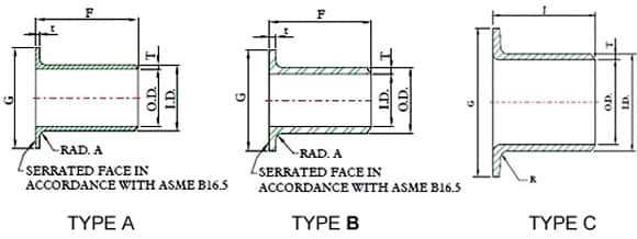
Common Types and Lengths
Stub ends dimensions and weight
Ends/Face lap finishing
Squared Ends
Flanged Ends
Victaulic Grooves
Threaded Ends (Male Only)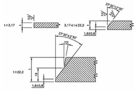
Standard
This is one of the reputed organizations in the world developing codes and standards.
The schedule number for pipe fitting starts from ASME/ANSI B16. The various classifications of ASME/ANSI B16 standards for different pipe fittings are as follows:
This is one of the largest voluntary standards development organizations in the world. It was originally known as the American Society for Testing and Materials (ASTM).
The Manufacturers Standardization Society (MSS) of the Valve and Fittings Industry is a non-profit technical association organized for development and improvement of industry, national and international codes and standards for: Valves, Valve Actuators, Valve Modification, Pipe Fittings, Pipe Hangers, Pipe Supports, Flanges and Associated SealsGeneral standard
Standard Specification ASTM A234 Standard Specification for Piping Fittings of Wrought Carbon Steel and Alloy Steel for Moderate and High Temperature Service ASTM A420 Standard Specification for Piping Fittings of Wrought Carbon Steel and Alloy Steel for Low-Temperature Service ASTM A234 WPB ASTM A234 is Standard Specification for steel pipe fittings includes carbon and alloy steel material for moderate and high temperature services. WPB is one of the steel grade in this standard ASME B16.9 ASME B16.9 Standard covers overall dimensions, tolerances,ratings, testing, and markings for factory-made wrought buttwelding fittings in sizes NPS 1⁄2 through NPS 48 (DN 15 through DN 1200). ASME B16.28 ASME B16.28 Standard covers ratings, overall dimensions, testing, tolerances, and markings for wrought carbon and alloy steel buttwelding short radius elbows and returns. MSS SP-97 MSS SP-97 Standard Practice covers essential dimensions, finish, tolerances, testing, marking, material, and minimum strength requirements for 90 degree integrally reinforced forged branch outlet fittings of buttwelding, socket welding, and threaded types. ASTM A403 Standard Specification for Wrought Austenitic Stainless Steel Piping Fittings. Wide variety for all areas of application
DIN EN ASME St 35.8 I
St 35.8 III
15 Mo 3
13 CrMo 4 4
10 CrMo 9 10
St 35 N
St 52.0
St 52.4P235GH-TC1
P235GH-TC2
16Mo3
13CrMo4-5
10CrMo9-10
X10CrMoVNb9-1
P215NL
P265NL
L360NB
L360NE
P355N
P355NL1
P355NHWPB
WPL6
WPL3
WPHY 52
WP11
WP22
WP5
WP9
WP91
WP92Chemical Composition (%) of ASTM A403
Steel No. Type C Si S P Mn Cr Ni Mo Other ób ós δ5 WP304 0.08 1 0.03 0.045 2 18-20 8-11 515 205 28 WP304H 0.04-0.1 1 0.03 0.045 2 18-20 8-11 515 205 28 WP304L 0.035 1 0.03 0.045 2 18-20 8-13 485 170 28 WP304LN 0.03 0.75 0.03 0.045 2 18-20 8-10.5 N2:0.1-0.16 515 205 28 WP304N 0.08 0.75 0.03 0.045 2 18-20 8-11 N2:0.1-0.16 550 240 28 WP309 0.15 1 0.03 0.045 2 22-24 12-15 515 205 28 WP310 0.15 1.5 0.03 0.045 2 24-26 19-22 515 205 28 WP316 0.08 1 0.03 0.045 2 16-18 10-14 2-3 515 205 28 WP316H 0.04-0.1 1 0.03 0.045 2 16-18 10-14 2-3 515 205 28 WP316LN 0.03 0.75 0.03 0.045 2 16-18 11-14 2-3 N2:0.1-0.16 515 205 28 WP316L 0.035 1 0.03 0.045 2 16-18 10-16 2-3 485 170 28 WP316N 0.08 0.75 0.03 0.045 2 16-18 11-14 2-3 N2:0.1-0.16 550 240 28 WP317 0.08 1 0.03 0.045 2 18-20 11-15 3-4 515 205 28 WP317L 0.03 1 0.03 0.045 2 18-20 11-15 3-4 515 205 28 WP321 0.08 1 0.03 0.045 2 17-20 9-13 Ti:5C-0.7 515 205 28 WP321H 0.04-0.1 1 0.03 0.045 2 17-20 9-13 Ti:4C-0.7 515 205 28 WP347 0.08 1 0.03 0.045 2 17-20 9-13 Nb+Ta:10C-1.1 515 205 28 WP347H 0.04-0.1 1 0.03 0.045 2 17-20 9-13 Nb+Ta:8C-1 515 205 28 WP348 0.08 1 0.03 0.045 2 17-20 9-13 Ta:0.1 515 205 28 WP348H 0.04-0.1 1 0.03 0.045 2 17-20 9-13 Ta:0.1 515 205 28 Notes:
Mechanical properties of ASTM A403
Grade UNS Tensile Strength, min Yield Strength,min Elongation min % in 4D ksi MPa ksi MPa Longit % Trans% ALL ALL 75 515 30 205 28 20 304L S30403 70 485 25 170 28 20 316L S31603 70 485 25 170 28 20 304N S30451 80 550 35 240 28 20 316N S31651 80 550 35 240 28 20 S31726 80 550 35 240 28 20 XM-19 S20910 100 690 55 380 28 20 S31254 94-119 650-820 44 300 28 20 S34565 115 795 60 415 28 20 S33228 73 500 27 185 28 20 What grade of steel is ASTM A403?
Benefits
Commercial benefits
the mechanical strength requirements of the piping systems.Installation benefits
has to be removed frequently, if positive isolation is a process requirement.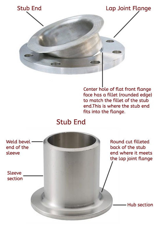
Stub Ends limitations
1. Limited Pressure Ratings:
2. Not Suitable for All Materials:
3. Vulnerable to Vibration and Movement:
4. Lack of Full Connection Strength:
5. Potential for Leakage:
6. Incompatible with High-Temperature Applications:
7. Restrictions in Pipe Movement:
8. Dependency on Flange Quality:
9. Not Ideal for Critical Applications:
10. Maintenance and Inspection Challenges:
11. Limited Applications in High-Corrosion Environments:
Why use Stub Ends?